Graph
slicer allows you to explore the control flow of a method and an inheritance graph of a class using a flow diagram.
This view can be opened in the context menu of a project entry (Open as -> Graph) or in the menu bar for an already opened view of a class file (View -> Graph).
Control flow
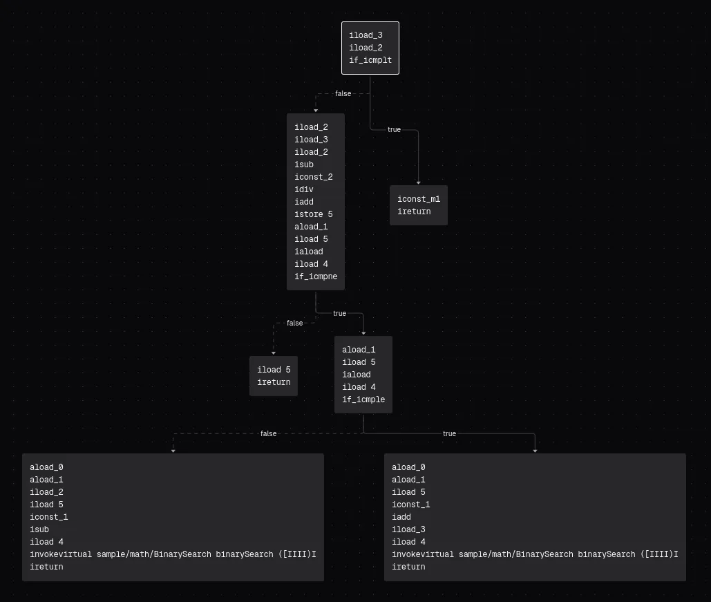
Section titled “Control flow”The control flow graph visualizes bytecode execution in a method using a top-to-bottom flow diagram.
If a graph has no nodes and no edges, it is likely an abstract method, which has no Code attribute.
A node is a block of instructions, which are executed sequentially. The node containing the zero-offset (first) instruction is called the entrypoint node and is highlighted with a special border (primary color of the UI - white, black, …).
Every node that does not naturally (without a jump) pass off execution to another node must end with a branch (if, goto, switch or subroutine jump) or terminal instruction (return, throw or subroutine return), otherwise it does not pass class file verification (execution fell off at end of code).
An edge is a line that connects the execution of two blocks in a specific direction. An edge can represent:
- a conditional/unconditional jump (a full line)
- a natural flow of execution between two consecutive nodes (a dashed line)
- a connection to an exception handler (a full red line)
Edges may also have hint labels, like:
true/false(“branch if comparison succeeds” instructions)default(switch instruction default branch)- an integer value (switch instruction branch case)
java/lang/Throwable(or any other exception type; exception handler)
A node typically has 1 (unconditional jump), 2 (conditional jump) or more (switch conditional jump) edges, but it can also have no edges, which means it’s dead code - it will never be executed.
Inheritance
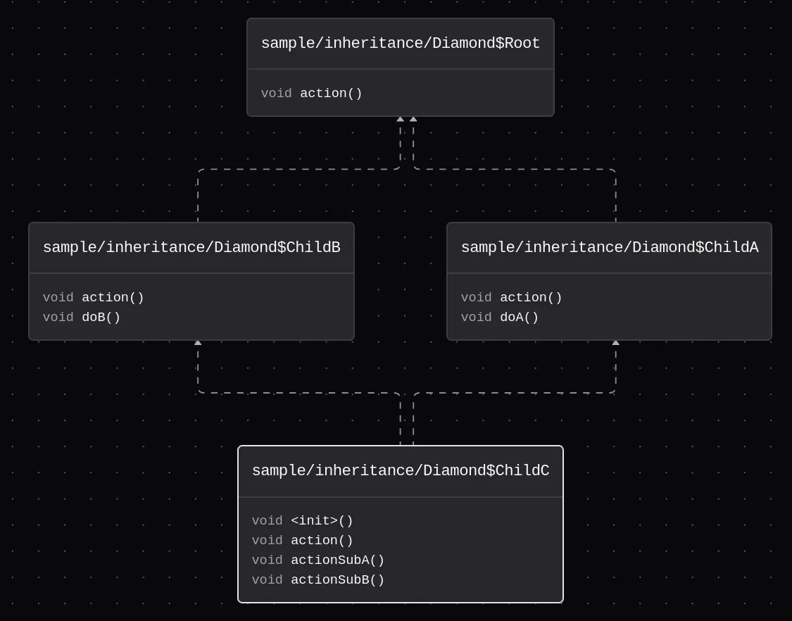
Section titled “Inheritance”The inheritance graph visualizes class inheritance and interface implementation using a bottom-to-top flow diagram.
A node is a block representing one class or interface. The node that represents the viewed class is highlighted using the primary color of the UI.
An edge is a line that connects two classes/two interfaces/a class with an interface. An edge can represent:
- class inheritance (
class Class1 extends Class2- a full line) - interface implementation (
class Class1 implements Class2- a dashed line)
Export
Section titled “Export”Graphs can be exported into SVG or PNG format in the context menu (right click -> Export).